EEG Electrodes: From active to passive, reference to ground
by Zainal Haberham and Tonny Mulder

Introduction
In EEG recordings there are diffrent types of electrodes that are used. On this page we will have a look at a few and explain how they work and what they do.
Select the topic that you are interested in, by clicking on the pictures of your choice
EEG Electrodes
There are basically two types of electrodes, active and passive ones. The major distinction is that in active electrodes the EEG is amplified at the scalp, whereas the passive electrodes are amplified in the (pre)amplifier at the end of the electrode wire. In general, the electrode and the wire it is attached to acts as an antenna. It picks up electric activity from computer monitors and other electrical and electromagnetic sources which is then being recorded as part of the EEG signal.
This ambient electrical activity, line noise at 50Hz (Europe) and 60Hz (North America) contaminates the EEG signal.
To minimize line noise it is beneficial to amplify the signal directly at the electrode, before it is send through the electrode wire. That principle is know as active amplification (Laszlo et al., 2014).
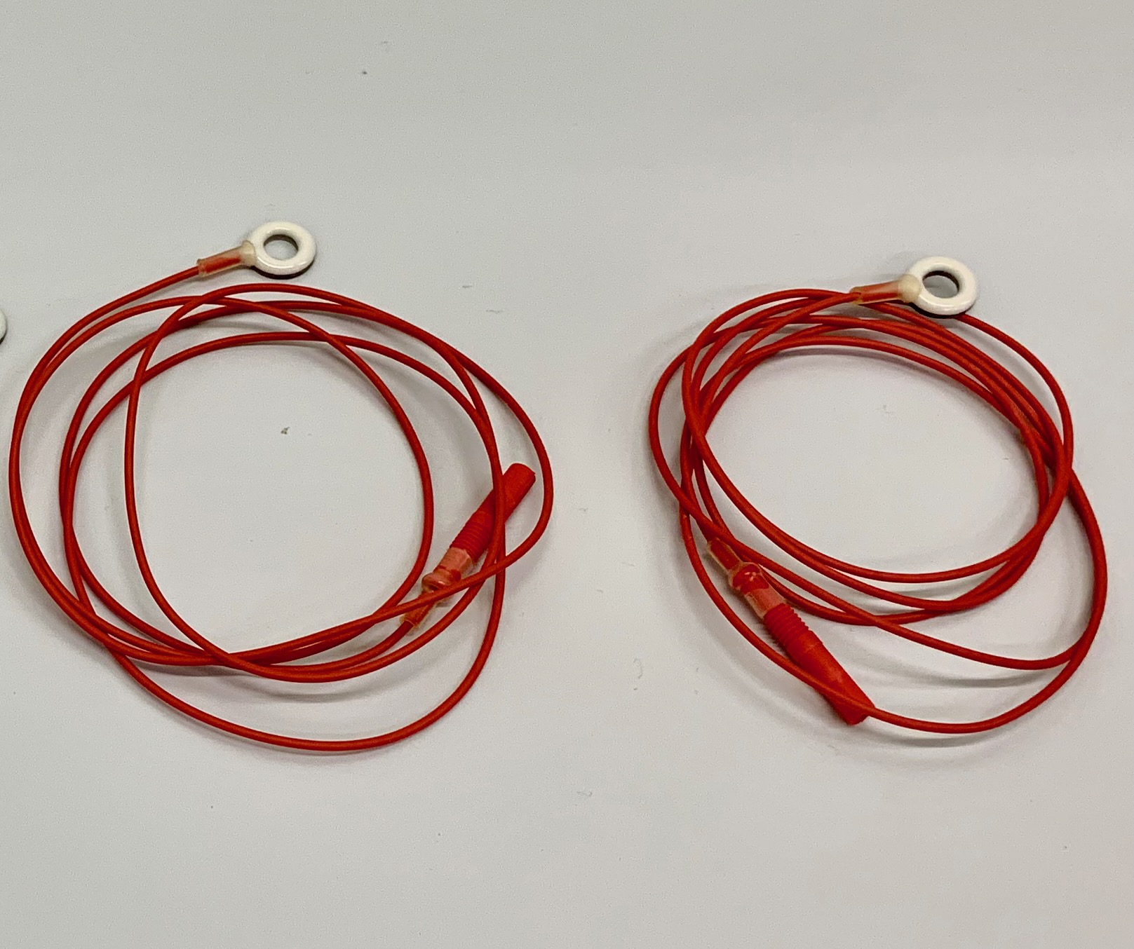
The recording electrodes used in this EEG practical are of the 'active' type.
The reference electrode
The EEG is an electric potential difference and to measure a 'difference' we need at least two electrodes. In principle, you can record a potential difference between any pair of electrodes: you measure the electric potential registered by one electrode in reference to the electric potential registered by another electrode. However, not every difference is equally interesting.
Imagine you record the potential difference between two electrodes you have placed immediately next to each other on the scalp. Most brain activity reaching the electrodes will be picked up more or less equally by both electrodes; the potential difference between the electrodes will therefore be close to zero.
Bipolar recordingThe only thing that remains is highly specific activity that reaches one electrode in a different way than it reaches the other, for instance something happening immediately below only one of the electrodes. This type of recording, in which you expect brain activity to be picked up by both members of a pair of electrodes, is called bipolar recording; both electrodes activily register activity and they can both be used as reference for the other.
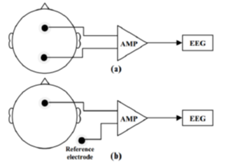
Figure 1: Bipolar (a) vs. Monopolar (b) montage. Note the neutral reference electrode in (b).
From Dietz et al., 2010.
doi: 10.1109/IEMBS.2010.5627451.
Now imagine you are interested in the gross electrical behaviour of a large part of the brain. Bipolar recording from two electrodes placed closely together would not work all that well, because most of the activity of interest is cancelled out as the signal difference between the electrodes is very small. Putting more space between the electrodes is possible, but given that both electrodes still pick up brain activity, interpreting the resulting differential signal would be rather complicated. A much simpler solution is placing one of the electrodes in a spot where you don’t expect any (well, any significant) brain activity to be picked up, for instance an ear lobe. That way your signal is the potential difference between a recording electrode (picking up brain activity) and a (more or less) neutral reference electrode. This is called monopolar (or unipolar) recording. Effectively you’re looking at what happens at only one “pole”, your active electrode.
Multiple recording electrodes, one referenceOf course, you are not limited to the use of only two electrodes. By combining a bunch of electrodes spaced out on the scalp with a single neutral reference electrode, it is possible to make a whole set of monopolar recordings giving information about the gross electrical activity emanating at those different scalp sites. It is of course equally possible to make a whole set of bipolar recordings, which, for example, may be helpful with source localization of an epileptic focus. It is even possible to recreate bipolar recordings from monopolar recordings by post hoc signal processing.
The reference electrodes used in this EEG practical are of the 'active' type.
The EEG setup in this EEG practical is a monopolar one with one reference electrode.
The ground electrode
In essence, two electrodes and a voltage amplifier constitute the bare minimum to carry an EEG signal from someone’s head to a data acquisition system (DAQ). The amplifier’s primary role is to make the weak scalp-recorded EEG signal strong enough to be read by the DAQ.
Single ended amplifierA single-ended amplifier has one input (the active EEG electrode), and references this input to its common potential (“common” in short), the common return path of the internal circuitry allowing current to flow. For non-biological applications, the common is often connected to the earth (the “ground connection”), which has the (arbitrary) potential of zero. In principle, it is perfectly possible to reference an EEG electrode to earth. However, for a variety of reasons (including the safety of the patient/test subject) it is not acceptable to do so. EEG amplifiers are therefore equipped with a so-called “floating ground”, a common signal ground which is isolated from the true earth ground. It takes its potential value from the average potential of the test subject’s body, by way of the reference electrode. In case of a single-ended amplifier circuit, the reference electrode and the signal ground are therefore one and the same. The main problem accompanying a single-ended circuit is its susceptibility to noise, primarily from capacitive coupling. Noise induced in the subject’s body and the signal wires is presented to the amplifier and gets amplified along with the signal. Add the noise that is induced in the amplifier itself, and the signal as a whole potentially becomes extremely noisy to the point of being unusable.
The signal presented to the DAQ is then: E(active) – E(reference) + noise
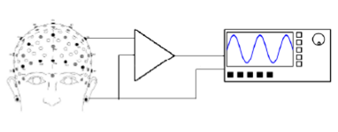
Figure 2: A single-ended circuit. The amplifier (triangular symbol) takes its input from an electrode on the scalp and sends the amplified output to a data acquisition system. The common signal return path takes its potential from the body of the test subject by way of a signal ground reference electrode on the ear lobe. Noise induced in the body and the signal wires is amplified along with the signal.
A simple, yet very effective solution is provided by the use of a differential amplifier. Essentially a differential amplifier can be considered to amplify the difference between the outputs of two single-ended amplifiers. To this end, a differential amplifier has two inputs, a “normal” (non-inverting) and an inverting input. If we’re interested in the potential difference between the active electrode and the reference electrode without the induced noise, we can largely eliminate this noise by introducing a separate signal ground electrode. The active electrode is connected to the non-inverting input, the reference electrode to the inverting input and the common signal return path is connected to the new signal ground.
The first half of the signal is similar to the situation with the single-ended amplifier; the amplified signal now is the electric potential difference between the active and ground electrodes, plus noise:
E(reference) – E(ground) + noise
The differential amplifier amplifies the difference between these two signals, which is:
E(active) – E(ground) + noise – (E(reference) – E(ground) + noise) =
E(active) – E(ground) + noise – E(reference) + E(ground) – noise =
E(active) –E(reference)
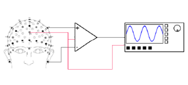
Figure 3: A differential circuit. The amplifier (triangular symbol) takes its inputs from the active electrode (non-inverting input, +) and the reference electrode (inverting input, -), and both inputs are referenced to a common signal ground (red). Everything common to both halves of the circuit is suppressed, resulting in an output that is the difference between the signals presented to the inputs.
In other words, everything that is common to both halves of the circuit of a differential amplifier is suppressed because the inverting and non-inverting inputs are out-of-phase. This is referred to as Common Mode Rejection (CMR). In order for CMR to be effective, it is essential that both halves of the circuit are closely matched. Susceptibility to noise is rather dependent on the impedances of the circuit. If, for instance, one electrode makes better contact with the subject than the other does, the electrode impedances differ, and therefore the amount of noise in both halves differ. In that case only part of the noise is common to both inputs, and some noise will therefore be amplified as well. A similar thing happens if one of the electrode wires crosses a power cord. The degree of capacitive coupling with the mains grid will be different from that of the other wires, leading to asymmetric noise in the circuits, and an asymmetric common mode. Be aware that this text presents a simplified explanation of the problem, with ideal components. Although real EEG amplifiers make ample use of cascading stages with differential amplifiers, their circuitry is far more complex and typically involves feedback loops to further attenuate the influence of EMI.
The ground electrodes used in this EEG practical are of the 'passive' type.
Confusing terminology
As seen in the example of a single-ended amplifier in the previous section, the difference between reference and ground electrodes is not always straightforward or clear. They may even be the same thing.
Occasionally alternative terms are used, which may add to the confusion; the ground electrode may be referred to as the “reference ground” or “ground reference” (because in both halves of the differential circuit, the respective inputs are referenced to the signal ground), and the reference electrode may then be referred to as the “active reference”.
Always check the Material and Methods section of a paperOccasionally, authors who aren’t inclined towards circuit design even confuse the terms completely, and this may have consequences for interpretation of the data. Carefully checking each paper you read for the exact montage is therefore recommended.
in unipolar recordings, the reference electrode is the one connected to a site where you don’t expect an EEG signal to be picked up, like the earlobes or the mastoid bone. Because of CMR, the exact placement of the signal ground is not all that critical, provided it isn’t placed so far away from the other electrodes that some huge potential difference may be picked up; for convenience’s sake it is usually placed on the scalp, between the recording electrodes. The term “active electrode” is also ambiguous. Often, the term simply refers to an electrode registering activity, in contrast to the ground and reference electrodes. However, “active” may also refer to the presence of power-consuming circuitry in the electrode itself (conversely, a “passive electrode” is an electrode with no active electronics inside). Noise can be further reduced by placing the first amplification stage as close to the electrode as possible, and because differential operational amplifiers are easily miniaturized, they physically fit inside the electrode housing.
The question whether or not a study was conducted using passive or active electrodes usually doesn’t interfere with interpretation or reproducibility of the data, but awareness of the different terminologies is generally advised.
For what it’s worth, the equipment used in the EEG practicals employs (electronically) active electrodes for the active and reference sites, and a passive ground electrode.
Signal vs Noise
The potential difference registered by a pair of electrodes does not only consist of brain activity. Various other internal and external sources contribute to the recorded signal, and their combined contributions may be referred to as (artefacts and) noise.
Noise from the electromagnetic environment
In electrophysiology, a major source of noise is generated by interference from the electromagnetic environment. In the present text, the term “noise” will be used to address this electromagnetic interference (EMI) only.
Direct current (DC, current flowing in a single direction) can only flow through a continuous conductor. Placing a capacitor (two conductors separated by a dielectric, a non-conductor) in circuit blocks the current flow completely. For alternating current (AC, current changing direction), the rules are different (Figure 4). Key point to remember is that alternating current is not completely blocked by an interruption of a circuit.
Noise from Capacitive coupling
In fact, it is possible to couple two distinct circuits by way of a capacitor; this blocks all direct current, but allows alternating current to pass. This so-called capacitive coupling is commonly used in electrical circuit design (Figure 5). Given that in essence a capacitor is simply two conductors separated by a dielectric, and AC circuits can be coupled by a capacitor, a problem becomes apparent. In a lab setting, we are surrounded by all kinds of electrical equipment hooked up to the same AC power supply, the 220V, 50 Hz mains grid. The human body is a conductor, all equipment we’re using consists of conductors, and everything is separated from everything by air, a dielectric. Effectively, everything in the lab is to some extent capacitively coupled. The alternating electric fields caused by current running through, for instance, the room lighting, induce tiny currents in the other conductors in the room (Figure 6).
Noise from Inductive coupling
In addition to capacitive coupling, inductive coupling can form another source of parasitic currents. An alternating current through a conductor generates an alternating magnetic field, which in turn is able to induce an alternating current in another conductor. This is the general principle behind a power transformer, but to some extent also applies in our lab setting. Inductive coupling can take place between fully isolated circuits, not connected to a common ground (Figure 7).
Noise from electromagnetic radiation
A further source of EMI noise is electromagnetic radiation, transmitted by e.g. wireless communication devices. The fluctuating electric and magnetic fields making up the EM waves induce currents in conductors, acting as antennas.
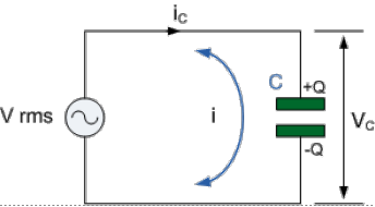
Figure 4: A capacitor in circuit. A DC voltage source simply charges the green capacitor (C), leading to a voltage across the capacitor (Vc) but no current (ic) flowing through it as soon as the capacitor is fully charged, i.e. shortly after turning on the voltage source. An alternating voltage source also charges the capacitor, but when the polarity of the voltage changes, the capacitor discharges and recharges accordingly. In effect, this leads to a constant alternating current flowing in the circuit.
From: http://www.electronics-tutorials.ws/capacitor/cap_8.html

Figure 5: Capacitive coupling. AC flows freely through circuits 1 and 2, but DC is blocked by the coupling capacitor.
From: https://www.sunpower-uk.com/glossary/what-is-capacitive-coupling/
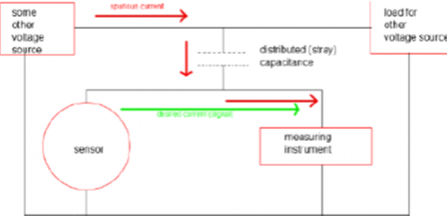
Figure 6: Unwanted (parasitic) capacitive coupling. The current drawn from some voltage source by some piece of equipment ("load for other voltage source") causes a parasitic current (red) to be added to the wanted (green) current in a piece of measuring equipment.
From: http://www.loopslooth.com/Capacitive%20coupling%20problem.html
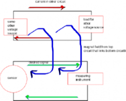
Figure 7: Inductive coupling. The large red current in the top circuit generates a magnetic field (blue), which induces a parasitic current superimposed on the desired current (green) in the measuring circuit.
From: http://www.loopslooth.com/Inductive%20coupling.html